More info on the project
In this video, we present a component that transforms a simple lathe into a gear-cutting machine.
Usually, gear manufacturing requires a combination of machines or even specialized machines for their creation. In fact, there are types of gears that are quite complex and require special machines and cutting tools. However, in machining workshops and generally in the construction of parts, machinery, and even in their repair, there are many instances where gear manufacturing is necessary.
So, we came up with a mechanism that can be mounted on the lathe we already have and, using it, we can manufacture the gears we need. In a previous video of ours, number 0137, we took motion from the lead screw responsible for thread cutting and managed, through the rotation of the chuck, to achieve corresponding rotation of a shaft on the other side of the lathe. By attaching a cutter to this shaft and rotating the workpiece with the chuck, we were able to shape the cylindrical shaft into an octagon, hexagon, square, and many more, depending on the cutter and speed settings.
In this case, we connected a 50:1 ratio gearbox to the output where we placed the cutter. This means that when the input rotates 50 times, the output of the gearbox makes one full rotation. With this in mind, we created a base that mounts on the lathe’s tool post, which carries this gearbox. So, when the gearbox is connected to the output and the chuck rotates, the gearbox mounted on the tool post also rotates accordingly.
This gearbox can move in all directions that lathe tools can—forward, backward, left, and right—while rotating. On the gearbox’s output, we installed a shaft on which the workpieces that will be machined into gears can be mounted.
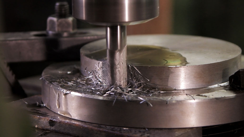
To produce gears of various sizes, we designed the tool in such a way that it can hold the workpiece in alignment with the chuck across all axes, allowing us to cut all types of gears depending on the cutting tools used. Thus, by placing the workpiece in this tool, the cutter in the lathe chuck, and selecting the correct gear settings, we can cut all gear types and tooth counts—as long as the material fits within our lathe.
We chose the 50:1 gearbox ratio and added a gear to the rear of the lathe so that when, for example, we place a 27-tooth gear on the output shaft, we can cut a gear with 27 teeth at the front. In this way, we can cut any number of teeth without needing complicated combinations.
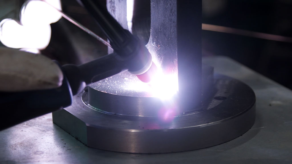
To cut a specific number of teeth, there were cases where we used plastic gears, which we cut with a CO₂ laser, or we had to make various combinations from the ones we had. Additionally, the combination of gears and speeds can result in cutting different sizes, such as Z25, Z50, Z75, Z100, without needing to change the lathe’s internal gears—only the speed setting needs to be changed.
Depending on the selected cutting tool, we can cut all gear modules. Gear cutting can also be performed using the lathe’s automatic feed, which utilizes the tool and improves ergonomics. The tool enables the production of a large number of gears in a short amount of time since it operates automatically.
During testing, we used our tool to make: spur gears, helical gears, bevel gears, bevel helical gears, and various other components. There is also the potential for automatic production of sprocket gears, timing belt gears, and many more, depending on the user’s choices and imagination.
After many hours of work, we are proud to present this tool and consider it one of our best creations.